Saturday, June 26, 2021

Resolving network latency issues with SQM


Over the past month I had been experiencing issues seemingly related to my ISP. Short periods of increased latency (lag spikes) were starting to have an effect on my sanity. After digging in several tools (a few that I knew about, a few that I didn’t before this endeavor), I was able to determine the cause of my issues (buffer bloat) and configure my router with Smart Queue Management (SQM) to resolve my latency issues.

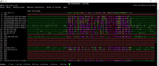
  1. Initial discovery of issues – I have ping alerts that send me a Pushover notification on my phone when an external endpoint is unreachable. In this case I’ve been pinging CloudFlare (1.1.1.1), and I started getting notifications that pings were dropping. Normally this would tell me that my internet is down, but in this case it was telling me something different. I tried to use pathping to determine the cause of pings dropping, but I couldn’t get it to see any hops outside my network. I used SS64 to find the Linux equivalent of pathping – MTR (Matt’s traceroute). Here we can see what appears to be packet loss at my ISP’s routing partner. Although this particular issue isn’t resolved by SQM, it lead me down the path I am on now…

    C:\Users\Ray\Pictures\2.png

  1. I reached out to Equinix support, and they told me that my ISP likely has an oversubscribed port. This means that the connection is basically maxed out, and the router drops ICMP packets as “bottom of the barrel” traffic. This StackExchange answer recommends to use the tool tcping, which is a wonderful network troubleshooting tool along with tcproute (this tool can help determine what firewall a port needs to be opened on, for example). They also recommended using WinMTR, but I found that it’s not that great because it counts “no ICMP reply” hops as packet loss, and it doesn’t have alternate display modes. So basically I’ve found that it’s good to have a mix of both Windows and Linux network troubleshooting tools at one’s disposal. Using tcping to probe DNS port 53, I was able to see that none of my actual data packets to CloudFlare were dropping. I decided to leave it at this, and ping monitor quad9 (9.9.9.9) until my ISP upgrades their oversubscribed link.


  1. But now that I’ve seen what can’t be unseen, of course other issues started cropping up. I was starting to see latency and packet loss during periods of high utilization. This would manifest as lag spikes either when I was working remotely, or listening to streaming audio. Using MTR’s alternate display mode (press the D key), I was able to see some pretty wild statistics across all the hops along the route. I had my ISP come out and take a look and they replaced the modem, and the signal looked fine. With this display mode you can see with the scale, that this was a period of extreme latency. ? is packet loss and > is greater than the labeled scale.
    C:\Users\Ray\Pictures\packetloss\Screenshot 2021-06-16 124155.png

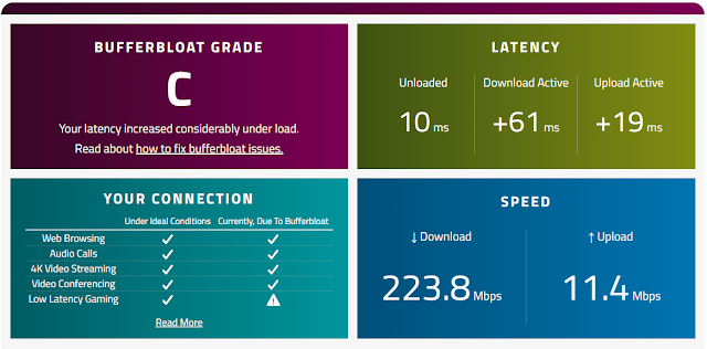
  2. Seeing that the very first hop to my router is even affected by extreme latency, I took some steps to rule it out. Pinging my router under heavy load showed latency that would seem to indicate the router is an issue. I looked up “EdgerouterX lag spikes” and I found several posts where the issue was described as “buffer bloat” and recommended to configure Smart Queue Management. I found the WaveForm buffer bloat test, and ran it on my network. It’s important to run this test directly connected to your router (with an ethernet cable) and with no heavy load on the internet connection. Bypassing my router, running the test directly from my laptop connected to the modem, I could see that the issue is not caused by my router. There are times when network congestion further down the route appears to back up and latency was much worse than this.

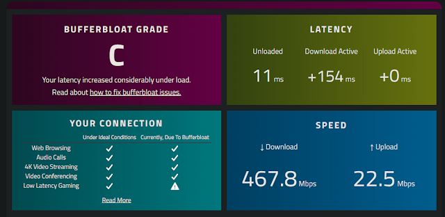
  3. Having done some research on SQM, I found that this has an impact on total available bandwidth. Knowing this I contacted my ISP and had them double my bandwidth to 400/20. In order for my EdgerouterX to pull bandwidth upwards of 300 Mbps, I had to configure my router to enable hwnat hardware offloading. Running a buffer bloat test, bandwidth is looking great, but still seeing latency occurring at times of congestion.
    C:\Users\Ray\Pictures\packetloss\before SQM.png

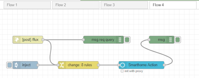
  4. I configured SQM on my router. It’s pretty simple… I did not need to use advanced settings, but it supports ECN if your other network equipment is capable.


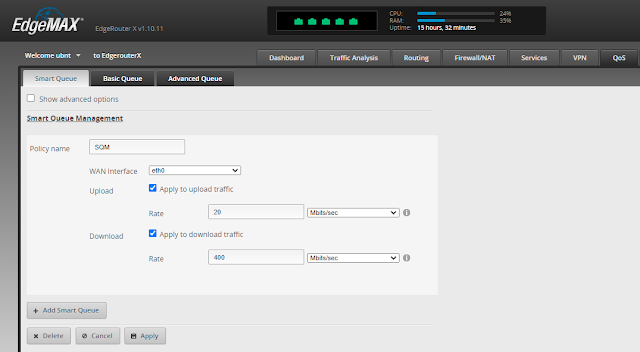
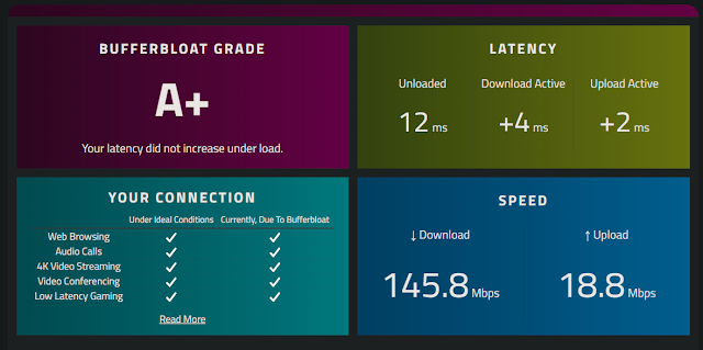
  1. After applying SQM and running another test, I see the desired effect – lower latency with the trade off of lower bandwidth (for a single connection). I am pretty sure however that with multiple connections SQM will still be able to saturate and fully take advantage of the data connection.  Update: SQM disables hardware offloading so the full speed on my router can't be realized while using SQM. I can either downgrade my internet connection or upgrade my router to a model that can offer more throughput with SQM enabled.
    C:\Users\Ray\Pictures\packetloss\after SQM.png


The takeaway: dropped pings don’t mean dropped data packets. If you have tools such as MTR or tcping at your disposal, they can help demystify network issues. If you’re seeing latency caused by buffer bloat, you need a router that can have Smart Queue Management configured. The ISP cannot be expected to have this feature enabled on their routers as it would be a bottleneck on the network. If you’re having trouble understanding buffer bloat, check out the FAQ on the buffer bloat test page. 


Wednesday, June 16, 2021

Using f.lux with Node-RED to control Alexa lights


Back in 2017, when f.lux released the HTTP API feature, I documented my findings with it but I didn’t know what exactly to do with it. I’m not going to link to it because it’s not that good. I had wanted the ability to control Alexa powered lights with Node-RED, but I gave up my search on this for quite some time apparently. After discovering the Alexa remote control functionality with the node-red-contrib-alexa-remote2-v2 node, and writing about using the Echo Button as a Toggle Switch, I realized I could finally do something with the f.lux HTTP API. So here’s how to do it:


  1. Make a HTTP in (POST) node and give it a URL suffix.

  2. In f.lux, go to options and smart lighting

  3. On the Connected lighting tab, enter the URL specified. It will be the Node-RED URL followed by the suffix specified. http://192.168.1.11:1880/flux

  1. Create a debug node, connect the HTTP node, and click the Deploy button (remember to do this moving forward any time you want to see the results from a change) and wait for the color temperature to change in f.lux. At this time manual changes to F.lux do not get posted to the HTTP interface. Using a debug output of msg.req.query you can see the values we will need to work with.

  2. You can capture the msg.req.query output of the debug node and save it for later testing
    {"ct":"6500","bri":"1.000000"}


  1. To get the control node ready, we need to install the node. Click on Manage palette in the top-right menu.

  2. Install the node-red-contrib-alexa-remote2-v2 node.

  3. Add an Alexa Smarthome node to the flow. Configure the Alexa account for the node and pick a device or group that you want to control. To configure the Alexa account you will need to open the URL provided after deploying the node, and access sign in to generate a cookie. This cookie is stored in a text file that you will need to specify and make sure you have permissions to write to. If lights stop being controlled you may need to manually refresh the cookie by signing in to the URL again.

  4. Add an inject node to the flow to trigger the remote node. Click the inject button, and note the entityId

  1. Create a change node. 1) Store msg.payload into msg.tmp, then delete msg.payload (many things require a payload with only the data that’s expected). 2) Set msg.payload[0].action to  3) Set the value for msg.payload[0].entity (the remote node takes an array format to send multiple control commands at once) to the entityId described earlier. Set msg.payload[0].action to msg.req.query.ct.

  2. Additionally, add rules to map the brightness value.


  1. Test the sample data by configuring the inject node you created with the sample data from earlier. {"ct":"6500","bri":"1.000000"}. Be sure to set the data type as number.

  2. Delete the test action from the remote node

  3. Click the inject button to test the data

  4. Now finally,  connect the HTTP node to the change node, and Deploy the flow (hopefully) one last time. Next time f.lux changes, the specified light should change and you’ll see the output in the debug logs (I waited for it – it works). In the future f.lux may be updated to ensure API push occurs even during manual changes. We may also see “Effects and extra colors” data available through the HTTP API. If they do, I will create an updated guide to include “mood lighting” with f.lux.


Monday, June 14, 2021

Use an Echo Button as a Toggle Switch


If you’ve used the Echo Button, you may have been disappointed like I was to find out that it’s a one-way switch. You can only use it to trigger a routine, and last I checked there isn’t a “toggle the light” routine. Well if you have one sitting around, you might be able to make use of it like I did. With Node-RED, you can use a flow to automate toggle switch functionality (and more!) for your Echo button. If you’re doing this you’ll need to make sure you have sudo/admin access to emulate an Echo device on port 80. For example with Docker you could just map an arbitrary container port to host port 80 (just like with iptables). This is the flow that I had working already, but I’ll be walking through step by step building it from scratch. For my setup I have two buttons: one on either end of my living space (bedroom connected to a home office upstairs), controlling both a Domoticz controlled device and an Alexa powered device.


1.       The most important thing for this to work are the node modules that both emulate/control echo devices. With Node-RED installed, click the menu icon at the top right, and select Manage palette


2.       Go to the install tab and install both of these modules: node-red-contrib-alexa-home and node-red-contrib-alexa-remote2-v2


3.       Drag and drop the controller node and the home node to the flow, and configure each.


4.       The controller configuration doesn’t need to be modified. If you are running as root/admin, and don’t have port  80 in use, you can set it to port 80 here. Otherwise you will need to forward the firewall port, for example in Linux.
sudo iptables -t nat -I PREROUTING -p tcp --dport 80 -j REDIRECT --to-ports 60000
sudo apt install iptables-persistant
sudo apt install iptables-save > /etc/iptables/rules.v4


5.       Name the device, especially if you have multiple buttons. Helps to also write a number on the bottom of the button. The type does not matter as we are not using the light features (but with this node, you could do something else neat like “turn my minecraft lights red”).


6.       You can output to the debug node to see the output at any point of the flow. Connect the node by clicking and dragging the connector icon from one node to another. Configuring the debug node can help when default debugging doesn’t quite cut it. Using complete message object is useful for capturing test payloads for writing JSONata functions (and other useful information). Debugging with msg.payload is usually fine. Using JSONata expressions you can filter the logs and format the output. Click Deploy at the top right to start the flow (and to update any time you’ve made a change). Node connection and deployment moving forward for documentation purposes is implied (you won’t be prompted to).  


7.       Discover the device by saying “Alexa, discover devices” (or using the app like I prefer when I shouldn’t have any reason to). Then in the app, toggle the newly discovered device. Here even though it shows “on” triggered true twice in a row, it seems there was a little bit of a lag for the callback to kick in after starting the flow (it later updated a lot quicker)


8.       To properly manage states a value needs to be stored. Create an inject node, and configure it to run once when the flow is started. Here, I am using payload.nvalue, which Domoticz also uses for control (but this guide does not cover that). One of the devices I am controlling with this flow uses Domoticz, so I can track the state of that device if it’s changed elsewhere. I picked the value of 1 as the default because I’m likely to be working on this stuff during the day when the lights are already on.

9.       Create a change node. Create a rule to set a flow context to the value specified in the inject node. This value is referenced later in the flow.


10.   On the Domoticz side, we have an MQTT node subscribing to the domoticz/out topic, a JSON node to convert the payload into an object, and a switch node, which only passes through the payload if it’s the Domoticz device specified. That completes the “initialization” part of the flow. One could feasibly include some nodes to manage the callback state of the virtual device on the Alexa side, but if you’re going to do that you may as well track the state of that light you’re controlling as well (playing better with voice commands). Otherwise, it’s no more than a couple button presses to sync the lights back to a given state.


11.   Create a change node. This is where the JSONata happens. I went into writing JSONata functions in one of my earlier entries. For ease of use an inject button is added to the flow to allow easy development. Also, being that not everyone uses Domoticz, I’ve adapted the flow by disconnecting my MQTT node, and adding a rule to update the flow value. 1) Delete msg.payload. This has to happen a lot of times because errors or other unexpected things can happen. If you need to work with the data from the payload in the same change node, just store it in msg.tmp or something, delete the payload, then do the thing. 2) The IDX is configured but this is for Domoticz only. 3) This JSONata function is used to invert the flow value. 3) The flow value is updated with the inverted value and passed to the next node(s)
$number($not($flowContext("button1"))) 


12.   For Domoticz all that is needed is to package up the payload into JSON format, and zap it over to MQTT. The device status gets updated on the Domoticz switch page. To toggle an Alexa controlled device, we are almost ready to call the node for that, but we need another change node (this could be consolidated into the same change node if you’re not using Domoticz). 1) The payload is stored in msg.tmp like previously mentioned, then deleted. 2) The remote control node expects a payload array, so make a rule for msg.payload[0].entity and leave it blank for now. 3) The JSONata conditional function needing to convert the boolean value to the control commands.
tmp.nvalue=1 ? "turnOn" : "turnOff"


13.   Add an Alexa Smarthome node to the flow


14.   Add an account, configuring as such that the authorization cookie can be stored in the text file. You may have to troubleshoot permissions if you don’t see the cookie data being stored in the file.


15.   Select one of the devices from your account and select a command so that we can fetch the ID.


16.   Use an inject node to trigger the remote node, and pipe that to your debug mode (complete message object). You now have your entityID. Paste it into the change node from earlier.


17.   Delete the command you used to fetch the ID, and deploy


18.   Your final product should now be an Alexa device that when triggered by a routine that is triggered by your Echo button, will toggle your Alexa powered light, even though it’s not technically supported.


19.   My Domoticz logs for the device show the activity, and the Alexa powered device I selected seems to reliably trigger when using an Echo button to trigger the routine


The takeaway: at a minimum, the Echo button can be used as a toggle button if you want it to. In reality, it could be used for a lot of things. Using a message router node (round robin) you could have a set of lights cycle through RGB colors (I didn’t have the ability to control Alexa powered devices years ago when I set this up). Instead of using the message router node, you could also use an array and a JSONata function to cycle through the values (I did both of these a while back with some AiLight custom firmware powered bulbs but did not save the flows). Also you could feasibly set up a rainbow mode, but if you’re triggering your lights to change with the Amazon API many times per minute, hours on end, I can’t speak towards that (rate limiting of the lambda functions behind the scenes; high usage may draw attention). In that case I would recommend getting some smart bulbs with the “rainbow mode” feature.

Don't forget to backup your flows! Menu -> Export -> All flows -> Download